Key Digital KD-WP8 Integration
Introduction
Mira Connect is an award-winning AV control system that makes it easy to build professional AV control systems. Mira Connect supports thousands of devices, making it easy to use in many different applications. Mira Connect also includes built-in equipment emulators, making it possible to create and experience, a full system before purchasing any AV equipment.
Mira Connect is configured through Mira Portal, the secure cloud management platform for Mira Connect that enables remote management for AV/IT teams.
In this guide we'll show how to use Mira Connect software, Mira Portal, and a KeyDigital KD-WP8-2 8-button keypad as the user interface to control a room using Mira Connect's room control API.
This guide shows you how to configure the keypad for volume and mute control, source selection, and a room power-off feature, as shown below.

There are two ways to configure a Key Digital keypad for use with Mira Connect Software:
Using the automatic export Key Digital configuration file feature built into Mira Portal
Manually creating a Key Digital configuration file by using the Key Digital keypad's built-in web interface
The built-in automatic export feature makes it easy to create a Key Digital keypad configuration file that can be imported and loaded into a keypad.
The manual method can also be used build entirely custom files or to the same steps can be used to modify a configuration file that was automatically generated by Mira Portal.
KeyDigital keypads include multiple sets of informative button labels and clear key caps that cover the button and labels to help users understand what each button does.
This guide is organized into five main sections:
Getting Started with Mira Portal and Mira Connect software shows how to create a Mira Portal account; how to create an organization, site, and room in Mira Portal; and how to add the equipment for this example to the room in Mira Portal.
Generating a Configuration File shows how to use Mira Portal to assign room control commands to buttons and then automatically generate a file that can be loaded directly into the keypad. This is the recommended path if you are looking to create a configuration file for a keypad.
Controlling Mira Connect shows how to create an API Key and how to get the display ID and source IDs required to switch video sources to a display.
Configuring the KeyDigital keypad shows how to define the buttons and how to define the events for the KeyDigital keypad. This section will provide all the details you need for configuring the keypad for this example. Follow this path if you'd like to see how to build a keypad manually. Don't forget to try generating a file automatically as described previously.
Using the KeyDigital keypad shows how to confirm operation, test, and troubleshoot the keypad's configuration.
Other Things You Can Do
While this article details one specific keypad and one application, the information presented here can be used to help you create an unlimited number of additional applications, create different keypad configurations with different functions assigned to buttons, or use different brands of keypads with Mira Connect's room control API.
Multiple keypads can also be used with Mira Connect software to provide multiple points of control in the room or to control different features of the room from different keypads. There is no end to the possibilities for using the Mira Connect Room Control API once you get started.
Now, let's get started!
Getting Started with Mira Portal
The Mira Connect AV control system is configured using Mira Portal, a secure cloud-based configuration and management platform. Mira Connect software includes an application programming interface (API) for controlling a room by sending simple and easy-to-understand commands to the Mira Connect software while Mira Connect does the work of controlling the underlying equipment.
Mira Connect Room Control API
Mira Connect's room control API is an application programming interface that allows control of Mira Connect from other applications. Mira Connect is the first control system that allows itself to be easily controlled, providing tremendous power and flexibility to programmers to add AV control into their applications or to use other user interface options for interacting with the room.
The room control API allows applications, or other devices, to send commands to Mira Connect over a network connection using web sockets or TCP connections. Mira Connect receives the commands, controls the underlying AV devices and reports status back to the application.
The benefits of using Mira Connect's Room Control API include:
Enables new applications and user interfaces while lowering the cost for adding room control to any AV application.
Reduces setup time, complexity, and troubleshooting for creating new applications because it is not necessary to know the API syntax of every device you want to control. The Mira Connect room control API works the same regardless of the underlying equipment used in the room since Mira Connect handles all the underlying device-specific details.
Allows you to extend the capabilities of simple user interfaces because Mira Connect can control equipment over TCP, UDP, HTTP, HTTPS, SSH, and perform advanced features that aren't easy (or even possible) to configure on simple user interface devices, including sending Wake-on-LAN packets to displays, scheduling room power-off, or simply synchronizing mute states across multiple devices.
Users have more flexibility to create custom user interfaces to meet the needs of their customers. Need a low-cost way to make it easy for users to switch sources while at a podium? Simply add a keypad.
In addition to any custom user interface, users can always access Mira Connect's professionally-designed native interface through the browser of their PC or mobile device.
Here's What We'll Be Setting Up
In this guide, we'll show how to use the KeyDigital KD-WP8-2 keypad's eight buttons as the user interface for controlling volume up and down, four video source selections, microphone mute, and to power off the room, as shown in the following figure.

The eight buttons will be configured with the following functionality:
Button
Behavior
Description
1
Volume Decrement
A single press will lower the volume by 1dB. Holding the button will continue to decrease the volume. The button will illuminate red when pressed.
2
Volume Increment
A single press will increase the volume by 1dB. Holding the button will continue to increase the volume. The button will illuminate blue when pressed.
3
Select source 1
When the button is pressed, source 1 is selected on the display. The button will illuminate blue when pressed Only one source button will be illuminated at any time.
4
Select source 2
When the button is pressed, source 2 is selected on the display. The button will illuminate blue when pressed Only one source button will be illuminated at any time.
5
Select source 3
When the button is pressed, source 3 is selected on the display. The button will illuminate blue when pressed Only one source button will be illuminated at any time.
6
Select source 4
When the button is pressed, source 4 is selected on the display. The button will illuminate blue when pressed Only one source button will be illuminated at any time.
7
Microphone mute
The button will mute all the microphones on the first press and illuminate red. On the second press, all the microphones will be unmuted and the LED will be turned off.
8
Room power off
The button must be held for 2 seconds before the room will be powered off. The button will illuminate red initially and after two seconds will turn blue. After two seconds all LEDs will be turned off.
If your application requires different functionality, you can follow these steps and further customize the keypad configuration and room control commands used.
We'll use the following steps to build our system with Mira Connect software as the control engine and a KeyDigital keypad as the user interface:
Step 1. Create a Mira Portal account or login to Mira Portal
Step 2. Add an Organization, Site, and Room in Mira Portal
Step 3. Install Mira Connect software on a local computer
Step 4. Pair the Mira Connect software to the room
Step 5. Add the equipment to the room
Step 6. Create an API Key and enable TCP control for Mira Connect
Step 7. Define the buttons on the KeyDigital keypad
Step 8. Configure the button events on the KeyDigital keypad
Step 9. Test the keypad configuration
Step 10. If necessary, troubleshoot the keypad configuration
You'll be able to manually create a configured keypad in less than 30 minutes the first time you do it. You will be more efficient on subsequent applications of the Mira Connect software and KeyDigital keypads.
You will be able to automatically generate a configuration file in Mira Portal in much less time.
Next, let's create a Mira Portal account or log in to an existing account.
Step 1 — Create a Mira Portal Account
If you don't already have a Mira Portal account, create a no-cost Mira Portal account. Otherwise, log in to your account. A valid email address is required to create an account.
Once a Mira Portal account has been created, follow the tutorial for creating an organization, site, and room. There are also training videos for how to create a Mira Portal account and how to add equipment to the room.
NOTE: As we go through this example, you can follow along using simulated equipment and confirm the operation with our Mira Connect Remote Control user interface in your browser.
While there is no cost to creating a Mira Portal account and for using Mira Connect room control API with simulated equipment, to use Mira Connect software with actual equipment, a room license is required and may be purchased through Mira Portal.
See our licensing information for more information and options for controlling real equipment.
Step 2 — Add an Organization, Site, and Room in Mira Portal
In Mira Portal, create an organization, and then add one or more sites to the organization. The tutorial that starts automatically will show you how to do this.
For each site, you can add one or more rooms. In this example, we'll create an organization called Example Organization, a site called My Site, and a room called Example Room.

Once we have created the room, we can install Mira Connect software, pair Mira Connect software to the room, and then add the equipment to control, as described in the following sections.
For more information on the equipment supported by Mira Connect and step-by-step instructions for how to add specific equipment to Mira Portal, see our integration guides.
Step 3 — Install Mira Connect Software
Mira Connect software is a software-only version of the Mira Connect AV control system that can be installed on any Windows® 10 or newer computer. Mira Connect software can be downloaded from AveoSystems.com.
Once downloaded, follow the instructions in the Mira Connect Software quick install guide to install the Mira Connect software.

Mira Connect software installs as a service and runs in the background, automatically restarting if the computer is rebooted. Mira Connect software also periodically checks for updates and will update itself automatically when there are new releases.
NOTE: Mira Connect software requires WAN access in order to be configured through Mira Portal. For more information on how to add WAN to your network, see our IT networks for AV professionals.
Step 4 — Pair Mira Connect to the Room
Once Mira Connect software has been installed, browse into the Mira Connect software at localhost: 52837 and click Get Pairing Code to get a pairing code that will let us associate Mira Connect with the desired room in Mira Portal.

Mira Connect software will connect to Mira Portal and get a unique pairing code. Note the pairing code will expire after an hour, after which a new pairing code can be requested.

Enter the pairing code into Mira Portal by clicking the PAIR button on the Mira Connect tab.

Once paired to the room, Mira Portal will show the updated status, as shown in the following figure.

Step 5 — Add Equipment to the Room
Continuing with this example, we'll use the following equipment as part of our room:
A Yamaha ADECIA DSP for mute and volume control
An AVPro video switcher for video switching multiple sources to a display
A Sharp display for displaying video sources in the room
Mira Connect makes it easy to use devices from a wide variety of manufacturers, allowing you to use the equipment that you are familiar with or to meet cost and delivery requirements.
Mira Connect software requires an advanced room license to control actual equipment in the room. An advanced room license may be purchased on Mira Portal for an organization and then assigned to the room. If you don't have a valid advanced license assigned to the room, you must choose to simulate the equipment to continue.

Once a room license has been purchased, the Licenses menu will show the new license information.

Navigate to the room and assign the license by clicking ASSIGN LICENSE and select the recently purchased license.

NOTE: While this application focuses on audio control and video source selection, it would be just as easy to control cameras (for example, recalling camera presets), launching speed dials to audio or video conferencing systems (including launching Zoom meetings), controlling lights and/or shades, selecting channel favorites on a TV Tuner, starting/stopping recording or streaming, and more.
With the Mira Connect Room Control API, regardless of the equipment you want to control in the room, the Mira Connect API commands are always the same. This makes it easy to use your favorite equipment without having to worry about the specific API commands needed to control that equipment. Mira Connect takes care of that for you.

The Yamaha DSP will be configured with a microphone mute and volume control, as shown in the following figure. In this example, we're using an array microphone that can be mounted in the ceiling and an analog output signal that will feed the loudspeakers in the room.
NOTE: For each family of products supported, Mira Portal provides a link to an integration guide with step-by-step instructions for how to configure the settings of that particular equipment in Mira Portal.
As mentioned earlier, if you don't have the equipment or a room license yet, you can choose Simulate Equipment to build the user interface and control system around Mira Connect's built-in equipment emulators.

The AVPro video switcher is configured with four inputs that we'll label as INPUT 1, INPUT 2, INPUT 3, and INPUT 4.

And finally, the Sharp display will be configured to use the HDMI 2 output from the video switcher connected to HDMI 1 input of the display.
NOTE: We used the 'Use sources connected to...' option on the display menu to access the output from the video switcher. See our training videos for more information about adding equipment and using video switchers with displays.

Finally, once the equipment has been configured, we'll edit the site settings for the 'My Site' site and enable the 'Show Power Off Setting' feature, as shown below. While you don't need this to use the set roomOff API command, we enable it so that we can see the 'Room power off' function in the remote control UI.

Once equipment has been added to the room, Mira Connect's user interface is created automatically and available via your browser by clicking the 'Remote Control' button.
The Remote Control feature makes it easy for AV and IT teams to manage rooms remotely from any location since they get access to the full user interface in the room and can remotely control the system.

Once we have completed all the steps to the keypad integration, we'll show you how you can control the system using the 'Remote Control' feature and how you'll also be able to see the affects of button presses made on the keypad.
Step 6 — Create a Mira Connect API Key
Once the room is paired to Mira Connect software, navigate to the API menu and click ADD API KEY. If you are going to be using different API keys for different applications, you can give each API key a different, appropriately-named label.

The API key value will be used in the commands that we send to the Mira Connect software to control the room. In this example, Mira Portal created an API key of ZBK2uGJ7r9whzTemLmSd . Click the 3 dots to the right of the API key to copy the key to your clipboard.
NOTE: The API key is case sensitive and is unique to your application and room. If you want to control Mira Connect from different applications, you can create different API keys, one for each application, or you can use the same API key across different applications.
If the API key is removed, all applications using that particular API Key will no longer be able to control Mira Connect as the commands will be refused by Mira Connect. Creating separate API keys for each application is a good practice and makes it easier for you to control access in the future.

Before using the API key, we must first ensure that TCP is enabled for the room in Mira Portal. Enabling TCP allows TCP communications to be created over port 52838 to the Mira Connect software.

In addition, if the PC running Mira Connect software is using a firewall, follow our step-by-step instructions to create an inbound firewall rule on the PC that will allow incoming connections over port 52838. By default, the PC may be blocking inbound communication to port 52838 from external devices until an inbound firewall rule has been created.
Mira Connect is now ready to be controlled.
Generating a Configuration File
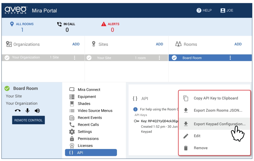
Once the room has been configured in Mira Portal, select the Export Keypad Configuration to assign room control commands to buttons.
Once the equipment has been configured in Mira Portal, assign the desired room commands to keypad buttons. For each button, select a room control command from the list. Select any options required for the command, such as the name of the display and the particular display source as shown in the following figure.
In this example, button 1 will be assigned to change the source of the Front of Room display to the source Room Computer. Mira Portal makes it easy to select any of the displays in the room and any of the sources associated with that display.

Once room control commands have been assigned to the buttons, click EXPORT KEYPAD CONFIGURATION to create the Key Digital keypad configuration file. The file is saved on your local PC with a default file name of: Key Digital KD-WP8V2-keypad-config.kwp.
Mira Portal Keypad Advanced Features
Mira Portal creates the keypad settings and customizes how the buttons work for certain room control commands.
Room power off - If adding room power off, the configuration will require the user to press the button for 2 seconds before the room is powered off. After the room is powered off, all the button LEDs will be turned off.
Video sources - If selecting multiple video sources, the buttons will automatically allow only one source to show selected, clearing a previous source selection.
Room Mute Toggle - The button will show red when the mute command is sent and not illuminated when the unmute command is sent.
Press and hold supported for volume up and down commands.
Once a configuration file is created and imported, you can also completely customize the file using the Key Digital web interface as described in our 'how to' guide for creating a configuration manually.
Import the Keypad File
Browse into the IP address of the Key Digital keypad and log in. The default password is 12345678.

Navigate to the IMPORT PROJECT tab and click Browse File and select the file that was exported by Mira Portal.

Next, load the configuration settings into the keypad by selecting the EXPORT / LOAD option and clicking the Load to Keypad button.

When presented with a confirmation, click Continue to load the configuration file into the keypad.

The configuration file is now running in the keypad.
If you have generated the configuration file, you can skip ahead to Step 9 — Testing the Keypad for how to test and troubleshoot the keypad.
Controlling Mira Connect
If you are manually creating a configuration file, then once we have an API key, you can start to use the room control API directly to configure buttons. For more information about the room control API, see the API command reference.
Continuing with our keypad example, we're going to use the following room control commands to control mute, volume, and source selection with Mira Connect:
Command
Description
set roomMute true
Mutes the room
set roomMute false
Unmutes the room
set roomVolumeInc -1
Decrements the room's volume by 1dB
set roomVolumeInc 1
Increments the room's volume by 1dB
set displaySource displayId value
Routes the specified source on a display
set roomOff
Powers off the room and resets the audio levels and mute
subscribe roomCaps filters: displays.*.sources
Gets the unique display ID and source IDs for this room to use with the displaySource command
There are many more API commands that can be used for other applications, including: recalling camera presets, triggering screen motion, adjusting lighting and shades, initiating recording, dialing speed dials, and much more. Anything Mira Connect can do can also be done using the Mira Connect room control API.
NOTE: Mira Connect's room control API command syntax is case sensitive. White spaces are used to separate commands and arguments. More than one whitespace character can be used.
Commands also support keyword arguments which have a key: value format.
Find the Display ID and Source ID Values
Each display and all sources defined for a display have unique IDs that can be used to reference those devices and sources with API commands.
To get the display ID and source ID values for the room, we'll send the subscribe roomCaps command. This command will report back all the capabilities of the room, including the unique display and source IDs. If a display is deleted and a new display is added in Mira Portal, then the display ID for the new display will differ from the original display ID. Similarly, if sources are removed and added back again, the new sources will have different source IDs.
To send the subscribe roomCaps command, we'll create a telnet session to the IP address of the computer running the Mira Connect software. If your computer does not support the telnet command, then we can use a telnet program, such as PuTTY, to create a telnet connection to the Mira Connect software at the computer's IP address and port 52838.
In this example, the Mira Connect software is running on a PC that has an IP address of 192.168.100.194.
After downloading and installing PuTTY, run the application and click Open to create the connection.

Once the connection is established, Mira Connect will automatically report back that the room is paired.

If the connection is refused, confirm the IP address and port number and ensure TCP is enabled in the room settings in Mira Portal as described previously. You may also need to create an inbound firewall rule following our step-by-step instructions.
Once the room is paired to Mira Connect, we'll send the subscribe roomCaps command to get information about the capabilities of the room. The subscribe command requires a filters argument that specifies which information we want to receive from the subscription. In this case, we'll filter the information to just the display source information for all displays in the room using the filter displays.*.sources. To get all the information, use the filter <bd>*</bd> . More information about subscriptions and filters is available in the Mira Connect Room Control API documentation.
While the room control API supports authenticating using the API key once per socket connection or with each command. In our application we'll send the API key with each command since it doesn't make sense to authenticate because each command sent by the KeyDigital keypad will create a new socket connection. To send the API key with each command we'll add the apiKey: keyword to each command.
NOTE: Since a new TCP socket is created for each command from the KeyDigital keypad, the apiKey: keyword must be included with each command. Remember to use your specific API key in the command — not the value used in this example.
The command we'll send to find the room capabilities in this example is:
Enter this command string and your specific API key into the terminal window and press the Return/Enter key.
Sending the subscribe command (shown below with the pink outline) will cause a response (shown below in the blue outline) to be returned by Mira Connect software with the current room capabilities.

The received roomCaps room capabilities information includes the source information for all displays in the room. If sources are deleted or added, or displays are added or removed in Mira Portal, there will be additional responses that are automatically generated that include the latest information about the room's capabilities.
We can copy the response and format the JSON response with a JSON formatter to make the response more readable, and we can also annotate the response as shown below.

As highlighted in the annotated response above,
The unique display ID for the display in the room is: -Nq395UIZPzYf29AVhAL
The unique source IDs that will be used for selecting those sources are:
Input 1: -Nq392rU18SLG_kX47NW
Input 2: -Nq392rU18SLG_kX47NX
Input 3: -Nq392rU18SLG_kX47NY
Input 4: -Nq392rU18SLG_kX47NZ
We'll use the display ID and source IDs in the commands as described in the following sections.
NOTE: The display IDs and source IDs are case sensitive and start with the '-' character. If displays or sources are added or removed, new IDs will be automatically reported via the roomCaps subscription. If you are not tracking changes to the roomCaps, then you can also send the
subscribe roomCapscommand again to get the latest values.
Now that we have the display ID and source IDs, we are ready to configure the KeyDigital keypad.
Configuring the KeyDigital Keypad
Creating a manual configuration for the KeyDigital keypad requires two main steps:
Defining the buttons, labels, and the types of button actions
Creating the events associated with the button actions
KeyDigital keypads support TCP socket connections from the keypad, allowing the keypad to send commands to Mira Connect. The keypad does not process any feedback from Mira Connect.
See Generating a Configuration File for automatically generating a configuration file. To create the configuration file manually, follow Steps 7 and 8.
Step 7 — Define the Buttons on the KeyDigital Keypad
Connect the KeyDigital keypad to a PoE ethernet connection to power up the keypad. Open your browser and enter the keypad's IP address.
NOTE: The keypad has a default IP address of: 192.168.1.239 with default password of 12345678. For more information about configuring the keypad, refer to KeyDigital's Setup Manual.
If you have configured the IP address for the keypad already, but don't remember the IP address, use a tool like Angry IP Scanner to discover the IP addresses of equipment on the local network. In this example, we used Angry IP Scanner to discover the keypad at 192.168.100.197 on our local network.

Once you have found the IP address of the keypad, browse to the keypad's IP address (192.168.100.197 in our example), enter the default password of 12345678, and click LOG IN.
Once logged in, the device info page will be shown. Here you can configure additional features of the keypad, including LED brightness and passwords.

For this example, we'll continue to the BUTTONS menu to start configuring the buttons for our application.
Button 1: Volume Down
We'll start with Button 1 and configure that as Volume Down.
We'll add a 'Hold for Repeat' function for repeating the command after being held for 0.5 seconds. This will make it easy to adjust the volume down by either pressing and holding the button or by repeatedly pressing the button.
While this button is pressed, our design will have it turn on the Red LED.
As shown in the following figure, we'll configure the button as follows:
Set the button name to Vol Down,
Select button type as Normal,
Configure the Button Press LED to be Red, and
Configure the hold for repeat with a 0.5 second hold time

Button 2: Volume Up
Button 2 will be configured as Volume Up.
Similar to the Volume Down button, we'll add a 'Hold for Repeat' function for repeating the command after being held for 0.5 seconds.
While this button is pressed, it will light up blue.
As shown in the following figure, we'll configure the button as follows:
Set the button name to Vol Up,
Select button type as Normal,
Configure the Button Press LED to be Blue, and
Configure the hold for repeat with a 0.5 second hold time
.

Button 3: Video Input 1
Button 3 will be configured to route Input 1 from the video switcher to the display. While there is no hold event for this button, we'll add support for a release event that will only leave one of the source selection buttons illuminated after the source has been selected. We'll configure these events in the event section.
While button 3 is pressed, it will light up blue. After releasing the button, the button will stay illuminated to indicate this source is selected.
As shown in the following figure, we'll configure the button as follows:
Set the button name to Src 1,
Select button type as Normal,
Configure the Button Press LED to be Blue, and
Set the release event to ON.

Buttons 4, 5, and 6 will be configured similarly as described below.
Button 4: Video Input 2
Button 4 will be configured to route Input 2 on the video switcher to the display. While there is no hold event for this button, we'll add support for a release event that will only leave one of the source selection buttons illuminated after the source has been selected. We'll configure the events in the event section.
When this button is pressed, it will light up blue.
As shown in the following figure, we'll configure the button as follows:
Set the button name to Src 2,
Select button type as Normal,
Configure the Button Press LED to be Blue, and
Set the release event to ON

Button 5: Video Input 3
Button 5 will be configured to route Input 3 on the video switcher to the display. While there is no hold event for this button, we'll add support for a release event that will only leave one of the source selection buttons illuminated after the source has been selected. We'll configure the events in the event section.
When this button is pressed, it will light up blue.
As shown in the following figure, we'll configure the button as follows:
Set the button name to Src 3,
Select button type as Normal,
Configure the Button Press LED to be Blue, and
Set the release event to ON

Button 6: Video Input 4
Button 6 will be configured to route Input 4 on the video switcher to the display. While there is no hold event for this button, we'll add support for a release event that will only leave one of the source selection buttons illuminated after the source has been selected. We'll configure the events in the event section.
When this button is pressed, it will light up blue.
As shown in the following figure, we'll configure the button as follows:
Set the button name to Src 4,
Select button type as Normal,
Configure the Button Press LED to be Blue, and
Set the release event to ON

Button 7: Mute
Button 7 will be configured to mute the room's microphones on the first press and to unmute the microphones on the second press.
As shown in the following figure, we'll configure the button as follows:
Set the button name to Mute,
Select button type as Toggle,
Configure the first button press LED to be Red to indicate the system is muted.
Configure the second button press LED to be Off to indicate the system is unmuted.
We'll configure the Toggle functions in the events section.

Button 8: Power Off
Button 8 will be configured to power off the room, but only after the button has been held for 2 seconds.
As shown in the following figure, we'll configure the button as follows:
Set the button name to PowerOff,
Select button type as Normal,
Configure the button press LED to be Red.
Configure a hold event as Hold for Send
Set the hold time to 2 seconds for our example.

Step 8 — Configuring Button Events
Once the buttons have been defined, the next step is to create the events that will send room control API commands to Mira Connect software.
Navigate to the EVENTS tab, and we'll configure the events for the buttons, as described in the following sections.
Events for Button 1: Volume Down
Button 1 will be configured to decrement the volume of the room.
As shown in the following figure, we'll configure the events as follows:
For Event 1:
Label the event as Volume Down.
Select the event type to IP Command.
Set the IP Type to TCP.
Set the IP address to the IP address of the Mira Connect PC: 192.168.100.194 in this example.
Set the IP port to 52838.
Set the Data Type to String.
Set the data to be the volumeInc command: set roomVolumeInc -1 apiKey: ZBK2uGJ7r9whzTemLmSd\r
While this example sets the increment of -1 dB to 'decrement' the volume, any valid value can be used.
This command explicitly includes the \r carriage return command terminator which has a value of 0x0D.
This command uses the apiKey specific to this room.
Set the Delay After Send value to 0.1 seconds.
The remaining events are left empty.

Events for Button 2: Volume Up
Button 2 will be configured to increment the volume of the room.
As shown in the following figure, we'll configure the events as follows:
For Event 1:
Label the event as Volume Up.
Select the event type to IP Command.
Set the IP Type to TCP.
Set the IP address to the IP address of the Mira Connect PC: 192.168.100.194 in this example.
Set the IP port to 52838.
Set the Data Type to String.
Set the data to be the volumeInc command: set roomVolumeInc 1 apiKey: ZBK2uGJ7r9whzTemLmSd\r
While this example sets the increment to 1 dB to 'increment' the volume, any valid value can be used.
This command explicitly includes the \r carriage return command terminator which has a value of 0x0D.
This command uses the apiKey specific to this room.
Set the Delay After Send value to 0.1 seconds.
The remaining events are left empty.

Events for Button 3: Video Input 1
Button 3 will be configured to route Input 1 of the video switcher to the display.
As shown in the following figure, we'll configure the events as follows:
For Event 1:
Set the button Action to Press.
Label the event as Src 1.
Select the event type to IP Command.
Set the IP Type to TCP.
Set the IP address to the IP address of the Mira Connect PC: 192.168.100.194 in this example.
Set the IP port to 52838.
Set the Data Type to String.
Set the data to be the volumeInc command: set displaySource -Nq395UIZPzYf29AVhAL -Nq392rU18SLG_kX47NW apiKey: ZBK2uGJ7r9whzTemLmSd\r
This example uses the display ID for the Sharp display and uses the source ID for the input 1 source.
This command explicitly includes the \r carriage return command terminator which has a value of 0x0D.
This command uses the apiKey specific to this room.
Set the Delay After Send value to 0.1 seconds.
The remaining events are left empty.

In addition, as shown in the following figure, configure a Release event to illuminate Button 3 and to turn off the LEDs on the other source selection Buttons 4, 5, and 6 as follows:
Set the button Action to Release.
For Event 1:
Set the Event Type to: LED Addition.
Set the Button Number to Button 3.
Set the LED Color to Blue.
For Event 2:
Set the Event Type to: LED Addition.
Set the Button Number to Button 4.
Set the LED Color to Off.
For Event 3:
Set the Event Type to: LED Addition.
Set the Button Number to Button 5.
Set the LED Color to Off.
For Event 4:
Set the Event Type to: LED Addition.
Set the Button Number to Button 6.
Set the LED Color to Off.

Events for Button 4: Video Input 2
Button 4 will be configured to route Input 2 of the video switcher to the display.
As shown in the following figure, we'll configure the events as follows:
For Event 1:
Set the button Action to Press.
Label the event as Src 2.
Select the event type to IP Command.
Set the IP Type to TCP.
Set the IP address to the IP address of the Mira Connect PC: 192.168.100.194 in this example.
Set the IP port to 52838.
Set the Data Type to String.
Set the data to be the volumeInc command: set displaySource -Nq395UIZPzYf29AVhAL -Nq392rU18SLG_kX47NX apiKey: ZBK2uGJ7r9whzTemLmSd\r
This example uses the display ID for the Sharp display and uses the source ID for the Input 2 source.
This command explicitly includes the \r carriage return command terminator which has a value of 0x0D.
This command uses the apiKey specific to this room.
Set the Delay After Send value to 0.1 seconds.
The remaining events are left empty.

In addition, as shown in the following figure, configure a Release event to illuminate Button 4 and to turn off the LEDs on buttons 3, 5, and 6 as follows:
Set the button Action to Release.
For Event 1:
Set the Event Type to: LED Addition.
Set the Button Number to Button 4.
Set the LED Color to Blue.
For Event 2:
Set the Event Type to: LED Addition.
Set the Button Number to Button 3.
Set the LED Color to Off.
For Event 3:
Set the Event Type to: LED Addition.
Set the Button Number to Button 5.
Set the LED Color to Off.
For Event 4:
Set the Event Type to: LED Addition.
Set the Button Number to Button 6.
Set the LED Color to Off.

Events for Button 5: Video Input 3
Button 5 will be configured to route Input 3 of the video switcher to the display.
As shown in the following figure, we'll configure the events as follows:
For Event 1:
Set the button Action to Press.
Label the event as Src 3.
Select the event type to IP Command.
Set the IP Type to TCP.
Set the IP address to the IP address of the Mira Connect PC: 192.168.100.194 in this example.
Set the IP port to 52838.
Set the Data Type to String.
Set the data to be the volumeInc command: set displaySource -Nq395UIZPzYf29AVhAL -Nq392rU18SLG_kX47NY apiKey: ZBK2uGJ7r9whzTemLmSd\r
This example uses the display ID for the Sharp display and uses the source ID for the input 3 source.
This command explicitly includes the \r carriage return command terminator which has a value of 0x0D.
This command uses the apiKey specific to this room.
Set the Delay After Send value to 0.1 seconds.
The remaining Press events are left empty.

In addition, as shown in the following figure, configure a Release event to illuminate Button 5 and to turn off the LEDs on buttons 3, 4, and 6 as follows:
Set the button Action to Release.
For Event 1:
Set the Event Type to: LED Addition.
Set the Button Number to Button 5.
Set the LED Color to Blue.
For Event 2:
Set the Event Type to: LED Addition.
Set the Button Number to Button 3.
Set the LED Color to Off.
For Event 3:
Set the Event Type to: LED Addition.
Set the Button Number to Button 4.
Set the LED Color to Off.
For Event 4:
Set the Event Type to: LED Addition.
Set the Button Number to Button 6.
Set the LED Color to Off.

Events for Button 6: Video Input 4
Button 6 will be configured to route Input 4 of the video switcher to the display.
As shown in the following figure, we'll configure the events as follows:
For Event 1:
Set the button Action to Press.
Label the event as Src 4.
Select the event type to IP Command.
Set the IP Type to TCP.
Set the IP address to the IP address of the Mira Connect PC: 192.168.100.194 in this example.
Set the IP port to 52838.
Set the Data Type to String.
Set the data to be the displaySource command: set displaySource -Nq395UIZPzYf29AVhAL -Nq392rU18SLG_kX47NZ apiKey: ZBK2uGJ7r9whzTemLmSd\r
This example uses the display ID for the Sharp display and uses the source ID for the input 4 source.
This command explicitly includes the \r carriage return command terminator which has a value of 0x0D.
This command uses the apiKey specific to this room.
Set the Delay After Send value to 0.1 seconds.
The remaining Press events are left empty.

In addition, as shown in the following figure, configure a Release event to illuminate Button 6 and to turn off the LEDs on buttons 3, 4, and 5 as follows:
Set the button Action to Release.
For Event 1:
Set the Event Type to: LED Addition.
Set the Button Number to Button 6.
Set the LED Color to Blue.
For Event 2:
Set the Event Type to: LED Addition.
Set the Button Number to Button 3.
Set the LED Color to Off.
For Event 3:
Set the Event Type to: LED Addition.
Set the Button Number to Button 4.
Set the LED Color to Off.
For Event 4:
Set the Event Type to: LED Addition.
Set the Button Number to Button 5.
Set the LED Color to Off.configure

Events for Button 7: Mute
Button 7 will be configured to mute the room microphones on the first press and to unmute the microphones on the second press.
As shown in the following figure, we'll configure the events as follows:
Set the button Action to First Press.
Label the event as MuteOn.
Select the event type to IP Command.
Set the IP Type to TCP.
Set the IP address to the IP address of the Mira Connect PC: 192.168.100.194 in this example.
Set the IP port to 52838.
Set the Data Type to String.
Set the data to be the mute command: set roomMute true apiKey: ZBK2uGJ7r9whzTemLmSd\r
This command explicitly includes the \r carriage return command terminator which has a value of 0x0D.
This command uses the apiKey specific to this room.
Set the Delay After Send value to 0.1 seconds.

In addition, configure a Second Press as follows:
Set the button Action to Second Press.
Label the event as MuteOff.
Select the event type to IP Command.
Set the IP Type to TCP.
Set the IP address to the IP address of the Mira Connect PC: 192.168.100.194 in this example.
Set the IP port to 52838.
Set the Data Type to String.
Set the data to be the mute command: set roomMute false apiKey: ZBK2uGJ7r9whzTemLmSd\r
This command explicitly includes the \r carriage return command terminator which has a value of 0x0D.
This command uses the apiKey specific to this room.
Set the Delay After Send value to 0.1 seconds.

Events for Button 8: Power Off
Button 8 will be configured to power off the room which will power off the display and reset the volume in the room to the middle of the range.
In this example, we'll also turn the button red when pressing it, and after the room power off command has executed, we'll turn off the LEDs on the video source selections, and after 0.5 seconds, we'll set this button's LED color to blue on to indicate the room power off function has executed.
Finally, we'll send the microphone mute command and set button 7 LED color to red to indicate the room is muted.
As shown in the following figure, we'll configure the events as follows:
Set the button Action to Hold for Send.
For Event 1:
Label the event as PowerOff.
Select the event type to IP Command.
Set the IP Type to TCP.
Set the IP address to the IP address of the Mira Connect PC: 192.168.100.194 in this example.
Set the IP port to 52838.
Set the Data Type to String.
Set the data to be the roomOff command: set roomOff apiKey: ZBK2uGJ7r9whzTemLmSd\r
This command explicitly includes the \r carriage return command terminator which has a value of 0x0D.
This command uses the apiKey specific to this room.
Set the Delay After Send value to 0.1 seconds.
For Event 2:
Set the Event Type to LED Addition.
Set the button number to Button 3.
Set the LED Color to Off.
For Event 3:
Set the Event Type to LED Addition.
Set the button number to Button 4.
Set the LED Color to Off.
For Event 4:
Set the Event Type to LED Addition.
Set the button number to Button 5.
Set the LED Color to Off.
For Event 5:
Set the Event Type to LED Addition.
Set the button number to Button 6.
Set the LED Color to Off.
For Event 6:
Set the Event Type to LED Addition.
Set the button number to Button 8.
Set the LED Color to Blue.
For Event 7:
Set the Event Type to Delay Addition.
Set the Delay Time to 0.5 seconds.
For Event 8:
Set the Event Type to LED Addition.
Set the button number to Button 8.
Set the LED Color to Off.
For Event 9:
Label the event as MuteOn.
Select the event type to IP Command.
Set the IP Type to TCP.
Set the IP address to the IP address of the Mira Connect PC: 192.168.100.194 in this example.
Set the IP port to 52838.
Set the Data Type to String.
Set the data to be the roomOff command: set roomMute true apiKey: ZBK2uGJ7r9whzTemLmSd\r
This command explicitly includes the \r carriage return command terminator which has a value of 0x0D.
This command uses the apiKey specific to this room.
Set the Delay After Send value to 0.1 seconds.
For Event 10:
Set the Event Type to LED Addition.
Set the button number to Button 7.
Set the LED Color to Red to indicate the system is muted.

Using the KeyDigital Keypad
Once the buttons have been configured, the keypad is almost ready to be used.
First, we must load the configuration into the keypad. To load the configuration, navigate to the EXPORT / LOAD option and click the Load to Keypad button to load the configuration into the keypad.
When presented with a confirmation regarding firmware updates after clicking Load To Keypad, click Continue. While this seems like an odd message, click Continue to load the configuration file into the keypad.
From the EXPORT / LOAD page you can also export the settings for the keypad to a .kwp file for backing up the keypad or for deploying to additional keypads.
In this example, the exported KWP file is shown below and available for download from here. You can see the file includes the volume, mute, display source, and room power-off commands and events.
NOTE: Advanced users can modify this file by changing the display ID, source IDs, and Mira Connect IP addresses when using the keypad with additional other rooms. Each room will have different display and source IDs and a unique API Key.

Once the button definitions and events have been loaded, the keypad is ready to be tested and used.
Step 9 — Testing the Keypad
To confirm operation, navigate to the VIRTUAL KEYPAD tab and press Button 1: Vol Down on either the actual keypad or on the virtual keypad shown on the VIRTUAL KEYPAD page. You should see the button turn red while pressed, and there should be a log entry, as shown in the following figure.
If the button is configured correctly, you will see that a TCP connection was created to Mira Connect at 192.168.100.194 and that the set roomVolumeInc command was executed successfully.
For each command sent, the keypad creates a TCP connection to Mira Connect software at port 52838, sends the command, and then closes the network connection.

Next, press Button 6 on the keypad to select input 4 on the display. The log will show the events associated with the button press and the set displaySource command. As configured, Button 6 changes the video source and illuminate blue once pressed. If the display is powered off when a source is selected, Mira Connect will automatically power on the display and then choose the desired source.

NOTE: You can also confirm the keys are functional by using the Mira Connect Remote Control feature in your browser. As commands are sent to select a source, you will see that the display has been powered on and that the source has been set to Input 4.
Continue testing each key on the keypad and notice that the Mira Connect remote control UI updates in real time as volume adjustments are made, the microphones are muted or unmuted, source selections are changed, and finally, when the keypad's room power off button is pressed and held for 2 seconds.
The KeyDigital Virtual Keypad page allows you to press buttons on the KeyDigital web interface and see the results of button presses on the physical keypad — as well as on Mira Connect's remote control user interface.

Step 10 — Troubleshooting the Keypad Configuration
If button presses are not affecting the room, look closely at the following items:
Ensure the keypad configuration has been loaded into the keypad as described in the Using the KeyDigital keypad section. After configuring the keypad, It's easy to forget to load the settings into the keypad. Trust me on this one.
If you are configuring multiple keypads, ensure you are working with the one you think you are working with by confirming the IP address of the keypad.
Ensure you are using a valid API key with each command string.
Get the API key from the room's API menu in Mira Portal, as described in the Create a Mira Connect API Key section.
Do not use the API key used in this document since that is specific to the room used to create this example and will not work with your room.
Ensure the event type for commands is set to IP Command and the IP Type is set to TCP.
Ensure the IP address of the Mira Connect software used in each of the command strings is set correctly.
Ensure the port for each command is set to 52838 and that TCP is enabled on the room in Mira Portal, as described in the Create a Mira Connect API Key section.
Ensure the Data Type is set to String, as described in the Configuring Button Events section.
Ensure each command includes the command terminator '\r'.
If these settings are correct, but there is still no communication with Mira Connect software, follow our step-by-step instructions for creating an inbound firewall rule on the PC that will allow incoming connections over port 52838. By default, the PC may be blocking incoming communication to port 52838 until an inbound firewall rule is created.
If mute and volume commands are functioning but video source selections are not working:
Ensure you have the correct display ID for the display from the
subscribe roomCapscommand. The display ID is unique to your equipment and your room. If you have a different room or delete the current and add a new display, the display ID will change.Do not use the display ID and source IDs from this example as they are specific to the room used to create this example.
Ensure you are using the correct source IDs for the sources from the
subscribe roomCapscommand. The source IDs are unique to this display. If you delete and add new sources in Mira Portal, the source IDs will change.
If button LEDs are not lighting as expected, confirm the LED selections and events in the Button and Event steps.
Summary
Mira Connect is an AV control system that makes it easy to build professional AV control systems for a wide variety of AV applications. To learn more about Mira Connect, see our website AveoSystems.com.
In this guide, we showed how to both automatically generate and import and load a configuration file for a Key Digital 8-button keypad and also how to manually create a configuration using Mira Connect's room control API. In both examples, different room control functions were added to buttons to create the user interface. We showed how to use different features of the KeyDigital keypad, including Press and Toggle features, Hold functions, and more.
You can use this example as the basis for your own applications and customize it to meet your needs.
Mira Connect is the only control system that has an API for controlling a room with simple-to-use API commands. Any feature from Mira Connect's user interface can be controlled via the room control API.
Mira Connect's room control API provides tremendous power to programmers who want to embed AV control with their applications without having to spend time deciphering and debugging different APIs from each manufacturers' equipment in the system.
As shown in the following figure, Mira Connect software controls the underlying devices using their individual control syntax, allowing an application to send consistent and simple commands to control the room regardless of the underlying equipment. Mira Connect also supports advanced features, including connecting to equipment using SSH, HTTPS, HTTP, UDP, and using Wake-on-LAN for powering on displays. Regardless of how Mira Connect connects to and controls equipment, your application only has to configure a TCP connection to Mira Connect, allowing your application to easily control devices that it never could before.

Using the room control API and similar steps, you can configure this and other network keypads, along with other third-party devices to control anything you'd like from Mira Connect. Using the power of Mira Connect software, you can easily control anything that Mira Connect touch panels can control and create your own user interface.
Want to learn more?
Contact us if you have an application for Mira Connect and would like to get more information.
To learn how to use the Mira Connect Room Control API, see our detailed Room Control API guide.
Last updated